- Joined
- May 13, 2023
- Messages
- 13
Lets get physical
So; you tried flashing your GPU and you didn't backup. Now you have some dude on the forum linking you a BIOS but you have no way to apply it because you don't have a spare GPU either. Well no worries friend. In this guide we are going to cover the simple procedures of recovering a BIOS with an eeprom programmer. Lets get a few things out of the way first.
It's pretty easy to get nervous or carried away when thinking about flashing a physical chip. Fear not though, once you grasp the concepts its really no different then using a USB drive. Before we cover the basics lets put your mind at ease.
How Much?
The first barrier of entry most people run into is that they think even attempting this is expensive. Lets be clear. It's not. We are not talking about this:

No, programmers come in many shapes and sizes and the type of chips they can handle can add complexity which can affect cost, but lets get to the skinny. It's not expensive. For programmers that can handle the kind of chips we will normally deal with they start at around $10usd to around $100usd for fancy things.
That's right. To fix your mistake or ensure you don't have one you literally need to spend less than $20usd. So what kind of hardware are we looking at? Lets take a look.
Time to get hard-ware
For the most part there are only a few big players.
FlashcatUSB: Flashcat is generally what I use. I own both the pro and classic editions. I prefer it when I am doing more advanced chips or JTAG work. Realistically its on the expensive side, especially if you are adding accessories. The software is good though and the product is quality. Downsides are its not very open source friendly, which means their can be cases where your chip needs to be manually input or you need to run a boundary scan. ($60USD)
CH341A: The cheapest of the lot and of varying quality this is what most will use. For between $11 and $20 USD the CH341A is affordable and robust. Unlike flashcat the CH341A uses opensource eeprom software. These software suites can vary in quality and chip support, but allows the flexibility to use whichever suite fits you the best. As an added bonus most of the time it comes with various adapters and extension cables that can come in useful at no extra charge. ($16USD)
TL866: TL866 is an older style programmer that can natively do physically larger chips. This programmer is generally used by hobbyists that work with vintage or older chips from the early compute era. However; its perfectly capable of handling newer chips with the same standard adapters the other two use. Given that its on the expensive side I would generally go with one of the other two but there really isn't anything wrong with this tool. ($35USD)
You cant go wrong with any of these, but since this guide is about accessibility we will write it using a CH341A. This is the one I bought. It was $12. It came with:
- 1 SOP8 test clip
- 1 8Pin to 8Pin converter
- 2 SOP8 SOP16 to 8Pin converters
- 2 2.54mm 4Pin connectors
So now that we know what we are using, what about the software? How will we write to the chip?
Burnin' For You
For software the CH341A has three primary contenders. They all serve the same basic functionality. In some cases one project may get updates before another and thus the supported chip lists can differ. Though that shouldn't be a real turn off as we will go over chip substitution later. Feel free to pick whatever tickles your fancy UI wise.AsProgrammer: This software is what most people will start with. For no other reason then it has a lot of references and has been around awhile. That doesn't make it inherently better given that software such as NeoProgrammer generally has a more upto date chip database. With that said its simple and clean and easy to understand. So this guide will also include it.
NeoProgrammer: Relatively new compared to AsProgrammer, NeoProgrammer takes a similar GUI and makes the buttons a little 2002. The chip DB at the time of writing has a few more manufacturers. Love it? Hate it? salt to taste.
SiberiaProg: The newest in the family of CH341A programming is SiberiaProg. This software is fugly. The end.
For the purpose of this guide we are actually going to go against the grain and use "AsProgrammer" the reason being our test flashes will be on chips that it does NOT have in its DB. This will be used to illustrate a worst case scenario where you need to substitute a chip model to get the job done.
Lets get the party started
Without further adieu lets get started. So basically, we will be working with eeprom. Not to be confused with ROM or EPROM most chips on motherboards and GPUs use EEPROM. This spelling is deliberate. Now between mobos and GPUs two primary types of chips are used.
SOIC8: Used on most GPUs. 8 legs soldered to PCB.
DIP8: Used on a lot of motherboards. 8 legs socketed.
There are of course other types of chips. 16+ pins socketed and unsocketed but the two above and their applications are the most common. Lastly are the voltages. As alluded to earlier there are two primary voltages that these chips operate on. Like the chip type (package) this can vary, but for the most part you will be touching either 3.3v or 1.8v chips. For now we wont worry about it. After all you might be reading this losing your mind because your GPU is dead.
Lets start with the reader itself. We will want to use the alligator clips. So lets get the clips and the adapter mounted on the machine.

For the most part we are going to want the clips in the 25xx position. You can see the position written on the PCB, or just like the picture. Closest to the USB slot.
")

As you may notice the clips have a single red wire. This is what we will be using as "Pin 1" on our BIOS chips.
All connected? Good lets get the driver installed. Now, like most programming software, its meant for different devices and tools. There is no one stop shop. So we will install the driver via device manager.

There it is! Isn't he cute?

Now right click and select "Update Driver" then navigate to the directory you have "AsProgrammer" in. Remember to unzip it first!


Now select the parent folder. (It will search sub folders for you.)

Now go ahead and hit "Next".

Nice! Now we can break things!


Down the rabbit hole
Now that we have the driver installed for our reader. Its time to connect our device. In my case we will be using an Intel A380 GPU. First we need to examine it to find the BIOS chip. This can be tricky; as mentioned they can some in different shapes and sizes. For the most part though they should look a little something like this.

If it helps the general manufacturers and the coding they use on the chip are:
Winbond (Winbond/W25)
Integrated Silicon Solution Inc (IS25)
Chingis Technology (Pm25)
PUYA (PUYA/P25)
In most cases you will come across a Winbond chip. Once you find it we want to connect to it. You know how USB A only fits one way? Same thing. We want to make sure pin 1, or in our case the red wire on our clip connects to pin 1 on the chip. How do we do that? Simple. They are marked. There will be a dot, physical or paint next to what "Pin 1" should be. In some cases like the picture above as one such example. You can also make out the arrow painted on the PCB pointing to PIN 1. Below is an example of a painted dot.

Neat.

Once you have it all connected it should look something like this. Notice how my red wire is visible? Make sure that it corresponds to the Pin 1 markings I explained above.

Now that we are all connected and plugged in. Lets open our programming software. We are going to want to read the chip to make sure we can talk to it, and to see if any info is on it.

Nice now go ahead and press the button. Oh man, nothing is happening and the logs at the bottom say this.

Looks like the chip isnt auto detected. Sad times. We need to write down or look at the photo that we took of the chip to get the name. You remembered to do that right? Perfect.
In my case the Asrock A380 uses a Winbond 25Q64JVSIQ. So lets see if we can go look for that in AsProgrammer.

Oh no! Our chip isn't listed! BUT thats ok! Welcome to the world of SPI programming. What we CAN do is look up the data sheet. Sometimes these include "Family" names. With these we can identify another chip on the list to use. Now in my case part of the name is "25Q64JV" Well we dont have a "JV" but we DO have "BV", "CV" and "FV". Lets just try one to see what we get. Select the chip from the list and attempt to read it again.
I got a bunch of gibberish


Sick! That's your BIOS my dude! Anything readable? Sometimes they sign it. Lets try "Intel"

Nice! Now lets do the responsible thing and back this up. I mean since your already here, its not a stretch to think you will save it in your recycle bin, but lets try to keep it somewhere safe. To do this we will just hit the "Save" button, since we already read the chip.

Look at you; you did it!

Alright, so now we have to fix your bad flash or otherwise put on your new BIOS right? Well slow your roll kid. We need to do some prelim stuff. Now when data is written sometimes the BIOS are smaller than the chip being written to. Get it? So if we have a bad flash or we are using a totally different BIOS we have no guarantee that everything will be over written, or even that there wont be extra bits left over. So what do we do?
We wipe the chip first.

Oh yeah bud, your gonna want to do that.

Now that its done, do me a solid and read the chip again.

Well how we do?

Oh yeah, this is hella broken now. Perfect. I like my chips squeaky clean. Now lets bring your stuff back to life. I am assuming you have a backup (lol you dont) or someone gave you one (thank them) so we are now going to hit the "Open" button and select our file.

Your programmers hex view should now fill with gibberish again.

Sick. Now we want to write all this data to the chip.

Oh yeah bud.

Now just sit back and be anxious for a bit. It should be noted, if you haven't noticed already your programmer probably has an LED like a hard drive light that blinks anytime you read, wipe, write to the chip. Go look at that if you need a distraction.

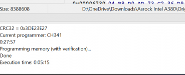
Oh snap our progress bar says done! Look at the log window!
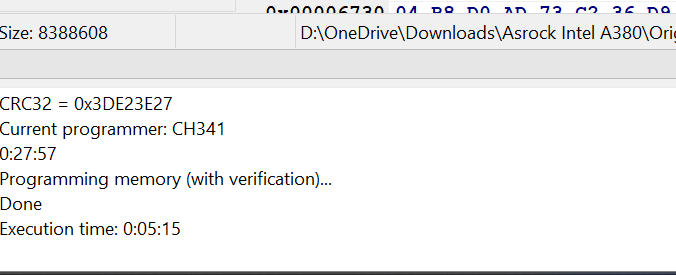
Sickkkk, now go plug your GPU in and enjoy playing PUBG badly.
It can all seem pretty complex but what did you really do? Lets break it down.
- You bought a tool for $11
- You installed a driver
- You attached a clip
- You pressed read
- You pressed erase
- You pressed write
At the end of the day invest in this now. Just backup your stuff in GPU-Z or spend $11 before you ruin hundreds worth of equipment. Might even be good just to have it on hand.
Q/A
Q: Can I apply this same technique to mobo BIOS?
A: Yup sure can! Any writable chip honestly. Flash your router firmware if you want. PS3 NAND, Stereo. Go nuts.
Q: Did you know you missed "save" in the bullet list at the end?
A: I didn't miss it. You and I both know your only here because you flashed from windows on your barely stable overclock and now your GPU is trashed.
Random Errors & Troubleshooting
I'll write the rest later, I'm tired and want to sleep.
Attachments

Last edited: